Abstract—Counters are a generally useful circuit that appear in many contexts. Because of this, the design space for clocked counters has been widely explored. However, the same cannot be said for robust clockless counters. To resolve this, we designed an array of constant response time counters using the most robust clockless logic family, Quasi Delay-Insensitive (QDI) circuits. We compare our designs to their closest QDI counterparts from the literature, showing significant improvements in design quality metrics including transistor count, energy per operation, frequency, and latency in a 28nm process. We also compare our designs against prototypical synchronous counters generated by commercial logic synthesis tools.
Keywords—counter; constant time; asynchronous; quasi-delay insensitive; qdi
Introduction
Counters implement an important piece of functionality with widespread use in both clocked and clockless designs, playing critical roles in the control logic for power gating, clock gating, and pipeline management [7][11][3]; for timers, performance counters, and frequency dividers [5]; and for iterative arithmetic circuits [6]. Its extensive utility draws intense optimization from commercial synthesis tools (like Synopsys Design Compiler and Cadence Genus) that take great care to optimize their structures during logic synthesis.
While clocked counters have been thoroughly explored such as the increment/decrement counter in [31], the increment/write in [27], and the decrement/write in [28][30], clockless counters have not. There are many clockless logic families [22], but this paper is limited to Quasi Delay-Insensitive (QDI) design [21] which has been successfully used in the past to implement many complex integrated circuits including microprocessors [8][9][7][11], FPGAs [12][4], and neuromorphic chips [10][2][1][5].
QDI design is widely regarded as the most robust of the families since correct operation is independent of gate delay. Circuits are partitioned into a system of components that communicate over message passing channels which are implemented by a bundle or collection of wires that carry both data and flow control information in the form of a request and an acknowledge.
This framework makes it easy to implement sophisticated control circuitry and exploit average-case workload characteristics to reduce energy usage and increase throughput. For counters, the more significant bits typically switch far less often, burning proportionally less dynamic power. This also makes it possible to carefully tune the circuit interface for specific timings. For example, a QDI counter can be designed to operate with a constant response time making its throughput independent from the number of bits. Such a clockless counter is also readily applicable to clocked environments because there is a strict upper bound on the delay between the input request and output response. Constant response time counters are not possible from standard clocked logic synthesis [24].
QDI circuits are often written in a control-flow language called Communicating Hardware Processes (CHP) described in Appendix A and then synthesized into a Production Rule Set (PRS) described in Appendix B using two basic methods.
The first, Syntax-Directed Translation [13][14], maps the program syntax onto a predefined library of clockless processes through structural induction creating a circuit that strictly respects the control flow behavior of the original program. Well formulated examples of this method are Berkel's constant response time decrementing counter with zero detection [24] and increment/decrement counter with zero/full detection [25].
The second, Formal Synthesis [18][20], iteratively applies a small set of formal program transformations like projection and process decomposition, decomposing the program until the resulting processes each represent a single pipeline stage. Then, these stages are synthesized using Martin Synthesis into production rules. This approach respects data dependencies, but not necessarily the original control-flow behavior of the specification [19]. This method was used to construct an increment/decrement counter with constant-time zero detection [32], which was then applied to power gate long pipelines in the ULSNAP processor [11].
In this paper, we use a well-known hybrid approach, Templated Synthesis [17]. First, we apply the formal transformations to decompose a CHP description for each of our robust, clockless, constant response time counters into Dynamic Single Assignment [23] CHP descriptions for each bit. Then, we apply various template patterns and micro-architectural optimizations to synthesize PRS which are then automatically verified and compiled into circuits. We compare our designs against published counters developed using Syntax-Directed Translation and Formal Synthesis, and show significant improvements in energy per operation as well as delay. We also show that our designs compare favorably to a standard clocked counter produced by commercial synthesis tools.
Our optimization rules, listed below, build upon Andrew Lines' Templated Synthesis method, starting with a flattened DSA CHP specification of a single pipeline stage process and deriving energy-efficient high-throughput PRS.
- Share logic between both computation and completion detection.
- Use the simpler Weak Conditioned Half Buffer template (WCHB) when possible.
- Group functionally equivalent behaviors prior to circuit synthesis.
- Use combinational gates when possible.
- Use our new template for internal state.
Each section will cover a different piece of functionality, giving the abstract specification in CHP and the final circuit implementation in PRS. Section 1 covers the increment, decrement, and clear commands along with constant time zero detection. Section 2 covers the read command. Section 3 covers the write command and Section 4 covers an interface circuit for the write command. Section 5 covers the stream command, and Section 6 discusses our evaluation of all of these counters, making concluding remarks. Finally, the appendices describe the notation we use.
Each counter will be named using the first letter of the commands and statuses
it supports. So idzn would be an increment/decrement
counter with zero/not zero detection. Further, an underscore separates channel
boundaries. So idzn would be a single channel with a 1of2 encoded
request: i and d and a 1of2 encoded enable:
z and n while id_zn would have two
channels each with a 1of2 request and dataless enable.
idczn: Increment, Decrement, Clear
Function
We'll start by assuming that the counter won't under or overflow. It starts
at zero, then for every iteration the status of the counter is sent across
Lz, a command is received from Lc, then the value, vn, is
either increased by one, decreased by one, or reset to zero depending upon the
command.
vn:=0;
∗[Lz!(vn=0); Lc?lc;
  [ lc=inc → vn:=vn+1
  ▯ lc=dec → vn:=vn-1
  ▯ lc=clr → vn:=0
  ]
 ]
To derive an implementable process for the least significant bit, we start
by separating the least significant bit, v0, of the value of the
counter from the remaining bits, vn. This requires that we
implement the carry circuitry for increment, decrement, and clear. If
Lc is increment and v0 is 1 or
Lc is decrement and v0 is 0, the
increment or decrement command should be carried to the remaining bits.
Otherwise, the remaining bits are left unchanged. Either way, the value of
v0 flips. If Lc is clear, then v0 will be
set to 0. If the remaining bits are already zero, then they will
be left unchanged. Otherwise, they will also be set to zero.
v0:=0, vn:=0;
∗[Lz!(v0=0 ∧ vn=0); Lc?lc;
  [ lc=inc → [ v0=0 → v0:=1
             ▯ v0=1 → v0:=0, vn:=vn+1 ]
  ▯ lc=dec → [ v0=0 → v0:=1, vn:=vn-1
             ▯ v0=1 → v0:=0 ]
  ▯ lc=clr → v0:=0; [ vn≠0 → vn:=0
                    ▯ vn=0 → skip ]
  ]
 ]
Then, we introduce two new channels: Rc to communicate the
carried command (inc, dec, clr) and Rz to respond with the
resulting status (zero, not zero). This removes all direct data dependencies
between v0 and vn so that we can apply projection.
v0:=0, vn:=0; (Rz!vn=0 ∥ Rz?rz);
∗[Lz!(v0=0 ∧ rz); Lc?lc;
  [ lc=inc → [ v0=0 → v0:=1
             ▯ v0=1 →
               v0:=0; Rc!inc; Rz?rz ∥
               Rc?rc; vn:=vn+1; Rz!vn=0 ]
  ▯ lc=dec → [ v0=0 →
               v0:=1; Rc!dec; Rz?rz ∥
               Rc?rc; vn:=vn-1; Rz!vn=0
             ▯ v0=1 → v0:=0 ]
  ▯ lc=clr → v0:=0;
             [ ¬rz → Rc!clr; Rz?rz ∥
                     Rc?rc; vn:=0; Rz!true
             ▯ rz → skip ]
  ]
 ]
Now, we can project the process into one that implements only the least
significant bit of the counter with variables v0, lc, rz and one
that implements the remaining bits with variables vn, rc.
v0:=0; Rz?rz;
∗[Lz!(v0=0 ∧ rz); Lc?lc;
  [ lc=inc → [ v0=0 → v0:=1
             ▯ v0=1 → v0:=0; Rc!inc; Rz?rz ]
  ▯ lc=dec → [ v0=0 → v0:=1; Rc!dec; Rz?rz
             ▯ v0=1 → v0:=0 ]
  ▯ lc=clr → v0:=0; [ ¬rz → Rc!clr; Rz?rz
                    ▯ rz → skip ]
  ]
 ] ∥
vn:=0; Rz!vn=0;
∗[Rc?rc;
  [ rc=inc → vn:=vn+1; Rz!vn=0
  ▯ rc=dec → vn:=vn-1; Rz!vn=0
  ▯ rc=clr → vn:=0; Rz!true
  ]
 ]
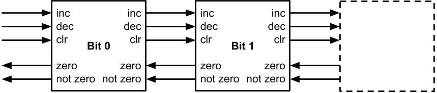
The specification for the remaining bits is left unaffected, and each bit
has four channels: Lc and Lz for the command and
counter status and Rc and Rz to carry the command to
and receive the status from the remaining bits. We can continue executing this
sequence of transformations recursively on the remaining bits to formulate an
N-bit counter.
The value pending on the Rz channel can be observed without executing a communication event by using a data probe as indicated by Rz. This allows us to rotate the communication actions on Rz so they always occur right before the associated communication on Rc. Finally, we flatten the specification into DSA format.
v:=0;
∗[ Lz!(v=0 ∧ Rz); Lc?lc;
   [ lc=inc ∧ v=1  → v:=0; Rz?; Rc!inc
   ▯ lc=inc ∧ v=0  → v:=1
   ▯ lc=dec ∧ v=0  → v:=1; Rz?; Rc!dec
   ▯ lc=dec ∧ v=1  → v:=0
   ▯ lc=clr ∧ !Rz  → v:=0; Rz?; Rc!clr
   ▯ lc=clr ∧  Rz  → v:=0
   ]
 ]
Because Lc and Lz, and Rc and
Rz always communicate together, they can be merged into
counter-flow channels L and R with the command
encoded in the request and the zero status encoded in the acknowledge as shown below.
However, our counter must be of finite size meaning we'll need to cap it off. We'll do this with a circuit attached to the most significant bit
(MSB) that sinks the command on Lc and always returns true on
Lz: ∗[ Lc?; Lz!true ]. This adds an overflow
condition to the previous counter specification.
vn:=0;
∗[Lz!(vn=0); Lc?lc;
  [ lc=inc → vn:=vn+1
  ▯ lc=dec → vn:=vn-1
  ▯ lc=clr → vn:=0
  ];
  [ vn > pow(2, bits) →
             vn:=vn-pow(2, bits)
  ▯ vn < 0 → vn:=vn+pow(2, bits)
  ▯ else → skip
  ]
 ]
At the moment, if the value of the counter is pow(2, bits)-1
(the value of each bit is 1), then an increment command and the
resulting status signal would have to propagate across the full length of the
counter. This means that the zero detection circuitry will take linear time
with respect to the number of bits in the worst case.
A constant time zero detection can be implemented by adding a third state to
the internal register, v. v=z represents that
this and all bits of greater significance are zero, v=0 represents
that this bit is zero but there is at least one of greater significance that
isn't, and v=1 represents that this bit is one. Now the internal
register can be used to calculate the counter status in constant time.
v:=z;
∗[ Lz!(v=z); Lc?lc;
  [ lc=inc ∧ v=1       → v:=0; Rz?; Rc!inc
  ▯ lc=inc ∧ v≠1       → v:=1
  ▯ lc=dec ∧ v≠1       → v:=1; Rz?; Rc!dec
  ▯ lc=dec ∧ v=1 ∧  Rz → v:=z
  ▯ lc=dec ∧ v=1 ∧ !Rz → v:=0
  ▯ lc=clr ∧       !Rz → v:=z; Rz?; Rc!clr
  ▯ lc=clr ∧        Rz → v:=z
  ]
 ]
This increases the maximum value the finite-length counter can store before
it overflows by pow(2, bits-1).
[ vn ≥ pow(2, bits)+pow(2, bits-1) →
           vn:=vn-pow(2, bits)
▯ vn < 0 → vn:=vn+pow(2, bits)
▯ else → skip
]
Implementation
Of the 7 conditions listed in the DSA CHP for each bit, conditions 1, 3, and
6 forward the command from Lc to Rc while 2, 4, 5,
and 7 don't produce an output. All conditions always acknowledge the input.
Conditions 1 and 5 always set v:=0, 2 and 3 set v:=1,
and 4, 6, and 7 set v:=z. Conditions 1 through 5 always change the
value of v but 6 and 7 might not. Finally Rz must be
true if v=z.
We start our WCHB template by defining the rules for the forward drivers.
Noticing that conditions 4 and 7 both set v:=z and don't forward
the command, we can merge them into a single forward rule, Rz.
v1 ∧ (Rz ∨ Rn) ∧ Li → Ri↾
(v0 ∨ vz) ∧ Li → R1↾
(v0 ∨ vz) ∧ (Rz ∨ Rn) ∧ Ld → Rd↾
v1 ∧ Rn ∧ Ld → R0↾
Rn ∧ Lc → Rc↾
Rz ∧ (v1 ∧ Ld ∨ Lc) → Rz↾
To understand what these production rules look like, we've rendered the
production rules for Ri↾ from above and Ri⇂ from
below as a CMOS gate structure in black with combinational feedback in
grey.
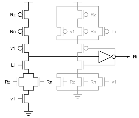
Ri as described by the production rules.Because there are 6 forward drivers, we'll need to use a validity tree.
However, we can use this to store the next value of the internal register by
defining _x0, _x1, and _xz. This makes
the rules for the internal register smaller and frees the reset phase of the
forward drivers from various problematic acknowledgment constraints.
Ri ∨ R0 → _x0⇂
Rd ∨ R1 → _x1⇂
Rc ∨ Rz → _xz⇂
¬_x0 ∨ ¬_x1 ∨ ¬_xz → x↾
The checks for v0, v1, and vz make
the input enable combinational removing the need for a staticizer and they can
be minimally sized since they are not on the critical path of the gate. This
kind of feedback structure is not possible in the typical WCHB template for
internal state found in [17].
v0 ∨ v1 ∨ x → Lz⇂
vz ∨ x → Ln⇂
Before using the validity tree to set the internal register, we have to wait for the input command to go neutral. This keeps all of the forward drivers stable while the register is written. The usual template in [17] doesn't allow simultaneous read/write of the internal state. We also make these three gates combinational using minimally sized transistors to remove the need for staticizers once again.
¬v1 ∧ ¬v0 ∨ ¬_xz ∧ ¬Lc ∧ ¬Ld → vz↾
¬v1 ∧ ¬vz ∨ ¬_x0 ∧ ¬Li ∧ ¬Ld → v0↾
¬vz ∧ ¬v0 ∨ ¬_x1 ∧ ¬Li ∧ ¬Ld → v1↾

(_xz ∨ Lc ∨ Ld) ∧ (v0 ∨ v1) → vz⇂
(_x0 ∨ Li ∨ Ld) ∧ (vz ∨ v1) → v0⇂
(_x1 ∨ Li ∨ Ld) ∧ (vz ∨ v0) → v1⇂
The reset phase of our forward drivers looks similar to that of a WCHB. However, checking the correct value of the internal register guarantees that the input request is neutral. This is because we check neutrality before writing the internal register and the internal register is guaranteed to change. This prevents the reset rules from becoming too long as tends to happen in a typical complex WCHB.
There are two rules, Rc⇂ and Rz⇂ from conditions
6 and 7, where this doesn't necessarily happen. Clearing an already zeroed
counter isn't guaranteed change the value of the internal register in the LSB.
This forces us to check Lc in the reset rules of the LSB.
Alternatively, we can assume that clearing an already zeroed counter is an
error and remove these two transistors.
¬Rz ∧ ¬Rn ∧ ¬v1 → Ri⇂
¬vz ∧ ¬v0 → R1⇂
¬Rz ∧ ¬Rn ∧ ¬vz ∧ ¬v0 → Rd⇂
¬v1 → R0⇂
¬Rn ∧ ¬v0 ∧ ¬v1 ∧ ¬Lc → Rc⇂
¬v0 ∧ ¬v1 ∧ ¬Lc → Rz⇂
Finally, the validity tree is reset and we can use the value of the internal register to return the status of the counter.
¬Ri ∧ ¬R0 → _x0↾
¬Rd ∧ ¬R1 → _x1↾
¬Rc ∧ ¬Rz → _xz↾
_x0 ∧ _x1 ∧ _xz → x⇂

¬v0 ∧ ¬v1 ∧ ¬x → Lz↾
¬vz ∧ ¬x → Ln↾
The dzn and idzn variations may be derived by deleting the unnecessary rules and their associated acknowledgments.
idrzn: Reading Counters
Function
Like the other commands, the read command will propagate from the LSB to the MSB. Each bit will send its value upon receipt the command, producing the counter value with skewed timing.
count:=0;
∗[Lz!(count=0); Lc?lc;
  [ lc=inc → count:=count+1
  ▯ lc=dec → count:=count-1
  ▯ lc=rd  → R!count
  ];
  [ count ≥ pow(2, bits)+pow(2, bits-1) →
                count:=count-pow(2, bits)
  ▯ count<0 → count:=count+pow(2, bits)
  ▯ else → skip
  ]
 ]
We'll build upon the implementation of the idzn counter. Upon receiving a
read command, it first forwards the command, then sends the bit value. Aside
from that, the rest of the command and detection circuitry in a given bit is
the same as the idzn counter.
v:=z;
∗[ Lz!(v=z); Lc?lc;
   [ lc=inc ∧ v=1       → v:=0; Rz?; Rc!inc
   ▯ lc=inc ∧ v≠1       → v:=1
   ▯ lc=dec ∧ v≠1       → v:=1; Rz?; Rc!dec
   ▯ lc=dec ∧ v=1 ∧  Rz → v:=z
   ▯ lc=dec ∧ v=1 ∧ !Rz → v:=0
   ▯ lc=rd              → Rz?; Rc!rd; O!v
   ]
 ]
Implementation
There are two practical methods to implement this read. For each method, we'll start with the idzn counter, showing only the rules that are added or changed.
QDI Read
The first takes an entirely QDI approach, sending the bit values through one bit QDI channels. We'll start by adding one rule for the read command which is always forwarded and a set of rules that output the read result.
(Rz ∨ Rn) ∧ Lr → Rr↾

v0 ∧ Oe ∧ Lr → Of↾
v1 ∧ Oe ∧ Lr → Ot↾
vz ∧ Oe ∧ Lr → Oz↾
Then, we add an extra validity check for the read result.
Rr ∧ (Of ∨ Ot ∨ Oz) → y↾

v0 ∨ v1 ∨ x ∨ y → Lz⇂
vz ∨ x ∨ y → Ln⇂
The rules for the internal register remain unchanged, and the forward drivers for the read are reset normally.
¬Rz ∧ ¬Rn ∧ ¬Lr → Rr⇂

¬Oe ∧ ¬Lr → Of⇂
¬Oe ∧ ¬Lr → Ot⇂
¬Oe ∧ ¬Lr → Oz⇂
The validity tree is reset normally, and the up-going rules for the input enable are lengthened to check for the neutrality of the read result.
¬Rr ∧ ¬Of ∧ ¬Ot ∧ ¬Oz → y⇂

¬v0 ∧ ¬v1 ∧ ¬y ∧ ¬x → Lz↾
¬vz ∧ ¬y ∧ ¬x → Ln↾
Bundled Data Read
The second method latches the bit values upon receipt of the command. When the command reaches the most significant bit of the counter, it is forwarded from the counter as the request signal for the newly generated bundled data read. This mixed QDI/Bundled Data approach is a fairly rare one. Most Bundled Data circuits have extremely simple pipeline structures and most QDI circuits avoid timing assumptions like the plague.
Much like the QDI read, we'll need to add a set of rules for the read command which is always forwarded. It will be fairly simple since it doesn't interact with much of the other circuitry.
(Rz ∨ Rn) ∧ Lr → Rr↾
Rr → _xx⇂
¬_x0 ∨ ¬_x1 ∨ ¬_xz ∨ ¬_xx → x↾
¬Rz ∧ ¬Rn ∧ ¬Lr → Rr⇂
¬Rr → _xx↾
_xz ∧ _x0 ∧ _x1 ∧ _xx → x↾
Then, if you don't care about the third value of the internal register,
vz, we'll need rules to merge it in with v0.
Dt = v1
v0 ∨ vz → Df↾
¬v0 ∧ ¬vz → Df⇂
Finally, the data, D, is latched using the read request.
Of ∨ Df ∧ Rr → Ot⇂
Ot ∨ Dt ∧ Rr → Of⇂
¬Of ∧ (¬Df ∨ ¬Rr) → Ot↾
¬Ot ∧ (¬Dt ∨ ¬Rr) → Of↾
This implements the most basic bundled data read which can handle another command in constant time after a read without problems unless it is another read. For two consecutive reads, the second will overwrite the latched values of the first before it finishes. So we have to delay the second read.
The easiest way is to add a communication event between the first and last bits in the counter for a read. So we'll need to modify the first bit to add this communication event.
Gr = Rr
Ge ∧ (Rz ∨ Rn) ∧ Lr → Rr↾
¬Ge ∧ ¬Rz ∧ ¬Rn ∧ ¬Lr → Rr⇂
Then we'll need to modify the end cap of the counter to handle this new dependency and to forward the request signal for the newly bundled data.
Lr ∧ Gr → Rr↾
¬Lr ∧ ¬Gr → Rr⇂

Re → Ra⇂
¬Re → Ra↾
¬Ra ∧ ¬Rr → Ge↾
Ra ∨ Rr → Ge⇂

Ra ∨ Li ∨ Ld → Lz⇂
¬Ra ∧ ¬Li ∧ ¬Ld → Lz↾

1 → Ln⇂
Now subsequent commands will be delayed only if there are two conflicting reads. This allows us to reduce the energy required by the system while only suffering a minor throughput hit.
dwzn: Writing Counters
Function
The write command operates much like the first method for reading. Propagate the command through the counter and have each bit write its value upon receipt of the command.
count:=0;
∗[Lz!(count=0); Lc?lc;
  [ lc=dec → count:=count-1
  ▯ lc=wr  → W?count
  ];
  [ count < 0 → count:=count+pow(2, bits)
  ▯ count ≥ 0 → skip
  ]
 ]
However, determining the location of the MSB is logarithmic with the
number of bits. To ensure this doesn't hinder the performance of the
counter, we will introduce a device that does this detection in parallel
in worst case linear time. This way we can do operations while the zero
detection for the write is taking place and the command can write
0, 1, or z directly to the
internal register.
v:=z;
∗[Lz!(v=z); Lc?lc;
  [ lc=dec ∧ v≠1       → v:=1; Rz?; Rc!
  ▯ lc=dec ∧ v=1 ∧ !Rz → v:=0
  ▯ lc=dec ∧ v=1 ∧  Rz → v:=z
  ▯ lc=wr              → Rz?; Rc!wr; W?v
  ]
 ]
Implementation
This implementation will build off the dzn counter, showing only the
rules that are added or changed. The production rules for the write are
structured similarly to the read. We have a signal Rw that is always
forwarded during a write, and then an input W that we save to Rw0,
Rw1, and Rwz.
(Rz ∨ Rn) ∧ Lw → Rw↾

Wf ∧ Rw → Rw0↾
Wt ∧ Rw → Rw1↾
Wz ∧ Rw → Rwz↾
Now, Rw0, Rw1, and Rwz stores the value to be written, allowing
us to lower the input enable immediately and use the built in method to
set the internal register.
Rw0 ∨ Rw1 ∨ Rwz → We⇂
Rw0 ∨ R0 → _x0⇂
Rw1 ∨ Rd → _x1⇂
Rwz ∨ Rz → _xz⇂
To ensure that the validity, x, is acknowledged we have to check
Lw when writing the internal variable.
¬v1 ∧ ¬v0 ∨ ¬_xz ∧ ¬Lw ∧ ¬Ld → vz↾
¬v1 ∧ ¬vz ∨ ¬_x0 ∧ ¬Lw ∧ ¬Ld → v0↾
¬vz ∧ ¬v0 ∨ ¬_x1 ∧ ¬Lw ∧ ¬Ld → v1↾

(Lw ∨ Ld ∨ _xz) ∧ (v0 ∨ v1) → vz⇂
(Lw ∨ Ld ∨ _x0) ∧ (vz ∨ v1) → v0⇂
(Lw ∨ Ld ∨ _x1) ∧ (vz ∨ v0) → v1⇂
The output signals are then reset normally using the Rw0, Rw1, and Rwz signals to
check the correct value of the internal register.
¬Rz ∧ ¬Rn ∧ ¬Lw → Rw⇂

¬Wf ∧ ¬vz ∧ ¬v1 ∧ ¬Rw → Rw0⇂
¬Wt ∧ ¬v0 ∧ ¬vz ∧ ¬Rw → Rw1⇂
¬Wz ∧ ¬v0 ∧ ¬v1 ∧ ¬Rw → Rwz⇂
Then the rest of the validity tree continues as usual and the input enable rules are left unchanged.
¬Rw0 ∧ ¬Rw1 ∧ ¬Rwz → We↾
¬Rw0 ∧ ¬R0 → _x0↾
¬Rw1 ∧ ¬Rd → _x1↾
¬Rwz ∧ ¬Rz → _xz↾
dwzn: Writing Counter Interface
Function
The zero detection block consumes an N bit base two integer and converts it to the three-valued format necessary for this counter.
Once again, we'll use a recursive implementation, pulling bit into its
own process so that it plugs into the W channel of the writing counter.
It simply propagates the zero detection from the MSB to LSB until it
either reaches a non-zero bit or the LSB. If every bit of greater
significance is zero and this bit is zero, then we forward true on the
Zo channel. If this bit is one, then we need to forward false.
∗[Wi?w; Zi?z;
  [ w=0 ∧ z=0 → Zo!0; Wo!0
  ▯ w=0 ∧ z=1 → Zo!1; Wo!2
  ▯ w=1       → Zo!0; Wo!1
  ]
 ]
Implementation
With this implementation, we can take advantage of early out to get
logarithmic average case complexity instead of linear. If Wi is true
or Zi is false, then we already know we need to forward false on
the Zo channel before we receive anything on the other channel. This
allows us to break the dependency chain, reducing the average propagation
time.
Upon receiving both inputs and setting the output on Wo, the input
enables are lowered and Zo reset. This leaves the value on Wo
unaffected while waiting for the counter, making the interface much less
costly in terms of throughput and response time because it can complete
its reset phase very quickly after Wo is finished.
Wie = Le
Zie = Le
Zoe ∧ (Zif ∨ Wit) → Zof↾
Zoe ∧ Zit ∧ Wif → Zot↾
Zif ∧ Wif ∧ Woe → Wof↾
(Zif ∨ Zit) ∧ Wit ∧ Woe → Wot↾
Zit ∧ Wif ∧ Woe → Woz↾
Zof ∨ Zot → _Zv⇂
Wof ∨ Wot ∨ Woz → _Wv⇂
¬_Zv ∧ ¬_Wv → Le⇂
¬Zoe ∧ ¬Zif ∧ ¬Wit → Zof⇂
¬Zoe ∧ ¬Zit ∧ ¬Wif → Zot⇂
¬Zif ∧ ¬Wif ∧ ¬Woe → Wof⇂
¬Zif ∧ ¬Zit ∧ ¬Wit ∧ ¬Woe → Wot⇂
¬Zit ∧ ¬Wif ∧ ¬Woe → Woz⇂
¬Zof ∧ ¬Zot → _Zv↾
¬Wof ∧ ¬Wot ∧ ¬Woz → _Wv↾
_Zv ∧ _Wv → Le↾
is_zn: Streaming Counters
Function
Finally, there are several applications where you might need to store a large number of tokens to be released later. For that purpose, we have an interface that converts the increment/decrement counter to a increment/stream counter in which one stream command will continuously produce tokens and decrement the counter until it is empty.
count:=0;
∗[ L?cmd;
   [ cmd=inc → count:=count+1;
     [ count≥pow(2, bits)+pow(2, bits-1) →
       count:=count-pow(2, bits)
     ▯ else → skip
     ]
   ▯ cmd=stream → Z!(count=0);
     ∗[ count ≠ 0 →
       count:=count-1; Z!(count=0) ]
   ]
 ]
The interface has three channels. The first channel, L, is the input request with increment or stream. The second channel, C, is an idzn channel that talks to the counter. The third channel, Z, responds with zero or not zero when the counter is being streamed. This interface is implemented by repeatedly producing decrement requests until the zero flag is set, at which point it acknowledges it's input request.
Cz?cz;
∗[ L?cmd;
   [ cmd=inc → Cc!inc; Cz?cz;
   ▯ cmd=dec → Z!cz;
     ∗[ ¬cz → Cc!dec; Cz?cz; Z!cz ]
   ]
 ]
Implementation
To implement this interface, the internal loop must be flattened into its parent conditional statement. Instead of just one condition for decrement, there are now two. One for decrement zero and one for decrement not zero.
Because the rules for Cd and Zf are the same, we make them the same node with no consequences. So this turns into a fairly simple buffer.
Cd = Zf

Ze ∧ Lf ∧ Cn → Cd↾
Ze ∧ Lf ∧ Cz → Zt↾
Lt ∧ (Cz ∨ Cn) → Ci↾

Zt ∨ Ci → Le⇂

¬Ze ∧ ¬Cn → Cd⇂
¬Ze ∧ ¬Lf → Zt⇂
¬Lt ∧ ¬Cz ∧ ¬Cn → Ci⇂

¬Zt ∧ ¬Ci → Le↾
This is the one type of counter that is not applicable to clocked environments. Because the input must wait until the counter empty before continuing and an output is not produced on a increment, this counter cannot be clocked.
Evaluation
We used a set of in-house tools to develop and evaluate these circuits. Production rule specifications are verified with a switch-level simulation which identifies instability, interference, and deadlock then automatically translated into netlists. These netlists are then verified using vcs-hsim. The CHP was simulated using C++ to generate inject and expect values which were tied into both the switch level and analog simulations using Python. This allowed us to verify circuit and behavioral correctness by checking the behavioral, digital, and analog simulations against each other.
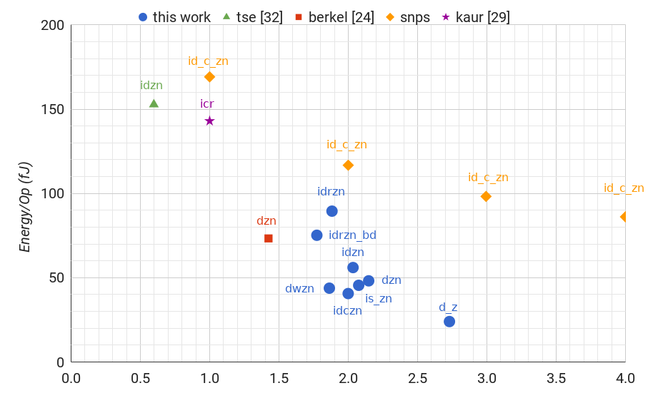
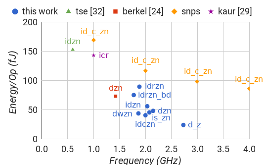
To evaluate frequency and energy per operation we simulated a 1V 28nm process on 5 bit instances of each counter with a uniform random distribution of input commands. Latency was measured from the 0.5v level of the input command to the 0.5v level of the detection event. To get more accurate results, we protected each of the digitally driven channels with a FIFO of three WCHBs isolated to a different power source. All counters are sized minimally with a pn-ratio of 2. In all of our implementations, we avoid using the half-cycle timing assumption (HCTA) [16]. However, it would be fairly easy to make the necessary modifications to take advantage of it. In all implementations, we use combinational feedback for C-elements. Circuitry necessary for reset was not included in any the above descriptions.
| Type | Trans | Frequency | Energy/Op | Latency |
|---|---|---|---|---|
| d_z | 50N | 2.73 GHz | 24.01 fJ | N/A |
| dzn | 102N+10 | 2.15 GHz | 48.17 fJ | 399 ps |
| idzn | 146N+12 | 2.03 GHz | 56.05 fJ | 421 ps |
| idczn | 174N+14 | 2.00 GHz | 40.62 fJ | 442 ps |
| idrzn | 246N+14 | 1.88 GHz | 89.51 fJ | 441 ps |
| idrzn_bd | 188N+32 | 1.77 GHz | 75.20 fJ | 441 ps |
| dwzn | 192N+12 | 1.86 GHz | 43.81 fJ | 487 ps |
| is_zn | 146N+61 | 2.08 GHz | 45.52 fJ | 139 ps |
We simulated [24] and [32] in the same 28nm process with the same minimal interface elements to get as close a comparison as possible. This allowed us to identify any functional differences between the two implementations as well.
[24] was closest to the dzn counter that we implemented. Though ours is limited to powers of two and uses only one channel. [24] can implement any max value and all three signals are split into separate dataless channels.
[32] was closest to the idzn counter that we implemented. However, instead of sending the zero status before receiving a command, they send the zero status after receiving a command, though this only matters for the first command. They also split the status signal and the command into two separate channels instead of one.
| Type | Trans | Frequency | Energy/Op | Latency |
|---|---|---|---|---|
| d_z_n[24] | 117N+32 | 1.42 GHz | 73.34 fJ | 468 ps |
| id_zn[32] | 398N+26 | 0.60 GHz | 152.76 fJ | 1150 ps |
Our counter template performs better in every metric operating 1.51 times faster than [24] and 3.38 times faster than [32] using 34% less energy than [24] and 63% less energy than [32]. Furthermore, our counter template is extensible to cover much more of the design space while [24] and [32] are limited to a single problem statement.
Finally, we wrote a simple id_c_zn counter in Verilog and
synthesized it using Synopsys Design Compiler (DC). Examining the verilog netlist, DC placed an array of
clocked registers which outputs to and receives inputs from a parallel
ripple-carry incrementer and outputs to a parallel zero detector. We
evaluated this using the same setup that we use to evaluate the other designs and our
equivalent counter uses 65% less energy at the same frequency.
| Type | Trans | Frequency | Energy/Op |
|---|---|---|---|
| id_c_zn | 74N | 1.00 GHz | 169.18 fJ |
| id_c_zn | 74N | 2.00 GHz | 116.75 fJ |
| id_c_zn | 74N | 3.00 GHz | 98.24 fJ |
| id_c_zn | 74N | 4.00 GHz | 86.12 fJ |
Conclusion
This paper presents an array of QDI constant response time counters for use in clocked and clockless systems showing a frequency and energy usage superior to many other designs. However, there are still a few things left to explore.
Combinations of detection signals including full, equal, less than, and greater than have yet to be explored. These could provide useful information regarding the state of the counter to the external system. Further, at the time of design a sufficient relative timing assumption framework and toolset was not available. It is plausible that significant performance and efficiency gains could be realized by applying such a framework to the designs found in this paper. Finally, some of these optimizations can be incorporated into a logic optimization tool for designing asynchronous circuits.
Appendix
CHP Notation
Communicating Hardware Processes (CHP) is a hardware description language used to describe clockless circuits derived from C.A.R. Hoare's Communicating Sequential Processes (CSP) [15]. A full description of CHP and its semantics can be found in [20]. Below is an informal description of that notation listed top to bottom in descending precedence.
- Skip
skipdoes nothing and continues to the next command. - Dataless Assignment
c↾sets the voltage of the nodectoVddandc⇂sets it toGND. - Assignment
a := ewaits until the expression, e, has a valid value, then assigns that value to the variable,a. - Send
X!ewaits until the expressionehas a valid value, then sends that value across the channelX.X!is a dataless send. - Receive
X?awaits until there is a valid value on the channelX, then assigns that value to the variablea.X?is a dataless receive. - Probe
Xreturns the value to be received from the channelXwithout executing a receive. - Sequential Composition
S; Texecutes the programsSfollowed byT. - Parallel Composition
S ∥ Texecutes the programsSandTin any order. - Deterministic Selection
[G1 → S1▯…▯Gn → Sn]whereGiis a guard andSiis a program. A guard is a dataless expression or an expression that is implicitly cast to dataless. This waits until one of the guards,Gi, evaluates toVdd, then executes the corresponding program,Si. The guards must be mutually exclusive. The notation[G]is shorthand for[G → skip]. - Repetition
∗[G1 → S1▯…▯Gn → Sn]is similar to the selection statements. However, the action is repeated until no guard evaluates toVdd.∗[S]is shorthand for∗[true → S].
PRS Notation
In a Production Rule Set (PRS), a Production Rule is a compact way to
specify a single pull-up or pull-down network in a circuit. An alias
a = b aliases two names to one circuit node. A rule G
→ A represents a guarded action where G is a guard (as
described above) and A is a dataless assignment as described
above. A gate is made up of multiple rules that describe the up and down
assignments. The guard of each rule in a gate represents a part of the pull-up
or pull-down network of that gate depending upon the corresponding assignment.
If the rules of a gate do not cover all conditions, then the gate is
state-holding with a staticizer.
References
Truenorth: Design and tool flow of a 65 mw 1 million neuron programmable neurosynaptic chip.IEEE Transactions on Computer-Aided Design of Integrated Circuits and Systems 34.10 (2015): 1537-1557.
Neurogrid: A mixed-analog-digital multichip system for large-scale neural simulations.Proceedings of the IEEE 102.5 (2014): 699-716.
BitSNAP: Dynamic Significance Compression for a Low Power Sensor Network Asynchronous Processor. Proceedings of the 11th IEEE International Symposium on Asynchronous Circuits and Systems (ASYNC), March 2005.
A split-foundry asynchronous FPGA.Custom Integrated Circuits Conference (CICC), 2013 IEEE. IEEE, 2013.
A digital neurosynaptic core using event-driven qdi circuits. Asynchronous Circuits and Systems (ASYNC), 2012 18th IEEE International Symposium on. IEEE, 2012.
An asynchronous divider implementation. Asynchronous Circuits and Systems (ASYNC), 2012 18th IEEE International Symposium on. IEEE, 2012.
SNAP: A sensor-network asynchronous processor.Asynchronous Circuits and Systems, 2003. Proceedings. Ninth International Symposium on. IEEE, 2003.
The Design of an Asynchronous Microprocessor.ACM SIGARCH Computer Architecture News 17.4 (1989): 99-110.
The design of an asynchronous MIPS R3000 microprocessor.Advanced Research in VLSI, 1997. Proceedings., Seventeenth Conference on. IEEE, 1997.
A digital neurosynaptic core using embedded crossbar memory with 45pJ per spike in 45nm.Custom Integrated Circuits Conference (CICC), 2011 IEEE. IEEE, 2011.
ULSNAP: An ultra-low power event-driven microcontroller for sensor network nodes.Quality Electronic Design (ISQED), 2014 15th International Symposium on. IEEE, 2014.
Highly pipelined asynchronous FPGAs.Proceedings of the 2004 ACM/SIGDA 12th international symposium on Field programmable gate arrays. ACM, 2004.
The VLSI-programming language Tangram and its translation into handshake circuits. Proceedings of the conference on European design automation. IEEE Computer Society Press, 1991.
Syntax-directed translation of concurrent programs into self-timed circuits. Computer Science Department at California Institute of Technology: Caltech-CS-TR-88-14, 1988.
Communicating Sequential Processes. Communications of the ACM, pages 666-677, 1978.
Reducing power consumption with relaxed quasi delay-insensitive circuits.Asynchronous Circuits and Systems, 2009. ASYNC'09. 15th IEEE Symposium on. IEEE, 2009.
Pipelined asynchronous circuits. California Institute of Technology Pasadena, CA, USA, 1998.
Projection: A Synthesis Technique for Concurrent Systems. Proceedings of the 5th IEEE International Symposium on Advanced Research in Asynchronous Circuits and Systems (ASYNC), pp. 125--134, April 1999.
Slack elasticity in concurrent computing.International Conference on Mathematics of Program Construction. Springer, Berlin, Heidelberg, 1998.
Synthesis of Asynchronous VLSI Circuits. Computer Science Department at California Institute of Technology: Caltech-CS-TR-93-28, 1991.
Compiling communicating processes into delay-insensitive VLSI circuits.Distributed computing 1.4 (1986): 226-234.
Asynchronous circuits.Springer Science and Business Media, 2012.
High-level synthesis of asynchronous systems by data-driven decomposition. Proceedings of the 40th annual Design Automation Conference. Proceedings of the 40th annual Design Automation Conference (DAC), pp. 508--513, June 2003.
VLSI programming of a modulo-N counter with constant response time and constant power. Proceedings of the Working Conference Asynchronous Design Methodologies, Manchester, U.K., 1993, pp. 1-11.
Handshake Circuits: an Asynchronous Architecture for VLSI programming. Vol. 5. Cambridge University Press, 1993.
Asynchronous loadable down counter. US Patent 8,027,425, September 27, 2011.
Programmable ripple counter having exclusive OR gates. US Patent 4,612,658, September 16, 1986.
Ripple counter with reverse-propagated zero detection. US Patent 5,060,243, October 22, 1991.
Low Power CMOS Counter Using Clock Gated Flip-Flop.International Journal of Engineering and Advanced Technology 2.4 (2013): 796-798.
High-speed architecture for a programmable frequency divider and a dual-modulus prescaler. IEEE Journal of Solid-State Circuits 31.5 (1996): 744-748.
Long and fast up/down counters. IEEE Transactions on computers 47.7 (1998): 722-735.
An Asynchronous Constant-Time Counter for Empty Pipeline Detection. jontse.com, 2009.
 Ned Bingham is a PhD student at Yale. He received his B.S. (2013) and
M.S. (2017) from Cornell. During his Masters, he designed a set of tools for
working with self-timed systems using a control-flow specification called
Handshaking Expansions. Currently, he is researching self-timed systems as a
method of leveraging average workload characteristics in general compute
architectures. Between his studies, he has worked at Intel on Pre-Silicon
Validation (2011, 2012), Qualcomm researching arithmetic architecture (2014),
and Google researching self-timed systems (2016). In his spare time, he reads
about governmental systems and dabbles in building collaborative tools. (www.nedbingham.com)
Ned Bingham is a PhD student at Yale. He received his B.S. (2013) and
M.S. (2017) from Cornell. During his Masters, he designed a set of tools for
working with self-timed systems using a control-flow specification called
Handshaking Expansions. Currently, he is researching self-timed systems as a
method of leveraging average workload characteristics in general compute
architectures. Between his studies, he has worked at Intel on Pre-Silicon
Validation (2011, 2012), Qualcomm researching arithmetic architecture (2014),
and Google researching self-timed systems (2016). In his spare time, he reads
about governmental systems and dabbles in building collaborative tools. (www.nedbingham.com)
 Rajit Manohar is the John C. Malone Professor of Electrical
Engineering and Professor of Computer Science at Yale. He received his B.S.
(1994), M.S. (1995), and Ph.D. (1998) from Caltech. He has been on the Yale
faculty since 2017, where his group conducts research on the design, analysis,
and implementation of self-timed systems. He is the recipient of an NSF CAREER
award, nine best paper awards, nine teaching awards, and was named to MIT
technology review's top 35 young innovators under 35 for contributions to low
power microprocessor design. His work includes the design and implementation
of a number of self-timed VLSI chips including the first high-performance
asynchronous microprocessor, the first microprocessor for sensor networks, the
first asynchronous dataflow FPGA, the first radiation hardened SRAM-based FPGA,
and the first deterministic large-scale neuromorphic architecture. Prior to
Yale, he was Professor of Electrical and Computer Engineering and a Stephen H.
Weiss Presidential Fellow at Cornell. He has served as the Associate Dean for
Research and Graduate studies at Cornell Engineering, the Associate Dean for
Academic Affairs at Cornell Tech, and the Associate Dean for Research at
Cornell Tech. He founded Achronix Semiconductor to commercialize
high-performance asynchronous FPGAs. (csl.yale.edu/~rajit)
Rajit Manohar is the John C. Malone Professor of Electrical
Engineering and Professor of Computer Science at Yale. He received his B.S.
(1994), M.S. (1995), and Ph.D. (1998) from Caltech. He has been on the Yale
faculty since 2017, where his group conducts research on the design, analysis,
and implementation of self-timed systems. He is the recipient of an NSF CAREER
award, nine best paper awards, nine teaching awards, and was named to MIT
technology review's top 35 young innovators under 35 for contributions to low
power microprocessor design. His work includes the design and implementation
of a number of self-timed VLSI chips including the first high-performance
asynchronous microprocessor, the first microprocessor for sensor networks, the
first asynchronous dataflow FPGA, the first radiation hardened SRAM-based FPGA,
and the first deterministic large-scale neuromorphic architecture. Prior to
Yale, he was Professor of Electrical and Computer Engineering and a Stephen H.
Weiss Presidential Fellow at Cornell. He has served as the Associate Dean for
Research and Graduate studies at Cornell Engineering, the Associate Dean for
Academic Affairs at Cornell Tech, and the Associate Dean for Research at
Cornell Tech. He founded Achronix Semiconductor to commercialize
high-performance asynchronous FPGAs. (csl.yale.edu/~rajit)